| actuators | (1) | (2) | (3) | (4) |
| b/w photo |
 |
 |
 |
 |
| color photo |
here | here | here | here |
| SMA (Nitinol) |
d=1.0 mm one-way wire |
d=1.0 mm one-way wire |
d=0.5 mm one-way wire |
d=6.5 mm two-way bar |
| actuation | one-way | one-way | one/two-way | one/two-way |
| More ... | details | details | details | details |
![]() Nitinol: NiTi Shape memory alloy To thermomechanical
behaviour of SMAs
Nitinol: NiTi Shape memory alloy To thermomechanical
behaviour of SMAs ![]()
| Design | Testing and simulation |
|
|
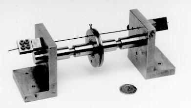
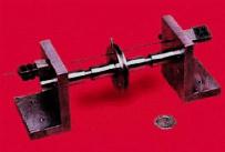
| The middle disk consists of a 7 mm thick steel annulus shrunk fit onto a SKF deep-groove ball bearing (o.d. 24 mm, i.d. 9 mm). In order to insulate both electrically and thermally the Nitinol wire from the steel disk, a series of Macor cylinders with 1.1 mm diameter holes in the centre are inserted into 5 mm diameter holes in the disk. Two specially designed clamps are used to fix the ends of the wire. A small preload can be applied on the wire by turning the square head of the clamp. A thin Tufnol layer is inserted between the shoulder of the actuator and the wire clamp, for electrical insulation. The shaft is not made as a single piece, but consists of four segments with a threaded head at one end and a threaded hole at the other end. Thus, both the one-disk and the three-disk configurations can be tested on the same hardware. The disks have an outer diameter of 48 mm with holes for the Nitinol wire at R = 18.5 mm from the centre of the shaft. | By applying a load which is heavy enough to induce transformation
in this d=1 mm Nitinol wire, the middle disk rotates (and in the mean time
Nitinol wire is elongated). This elongation of the Nitinol wire can be
recovered by heating, i.e. passing an electrical current through it. Therefore,
this actuator rotates forwards in heating and backwards in cooling.
Several tests were carried out on this one-way actuator, both in the one-disk and three disk configurations. The applied torque were 2.3 Nm and 3.2 Nm. The behaviours were also simulated by using phenomenological constitutive model which taking temperature non-uniform alone Nitinol wire into consideration. |
| Design | Testing and simulation |
|
|
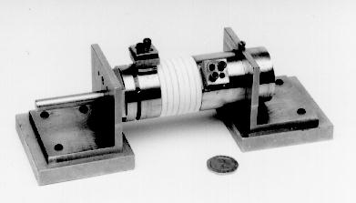
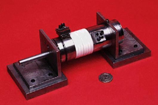
| Up to 7 disks, thickness 5 mm and outer diameter 39 mm, can be mounted on SKF deep groove ball bearings. The diameter of the steel shaft is 8 mm. The shaft is rigidly connected to the left-hand block. A free-turning steel block, mounted on two ball-bearings like those used for the Macor disks, provides a clamping point for the Nitinol wire. The loading system is also attached to this block. To further reduction the friction between Nitinol wire and Macor disks, and to prevent Nitinol wire falling into gaps between disks. PTFE sleeves (o.d.= 3.14 mm) are used (not shown in the left plot). |
A d=1 mm diameter Nitinol wire is stretched either before mounted on
the actuator by means of hanging a weight on its end or after mounted on
the actuator by means of applying a torque on the right end-block. As an
electrical current passing through it, temperature increases and Nitinol
wire shrinks. This causes the rotation of the right end-block. This actuator
can only act once each time. After one performance, Nitinol wire has to
be re-stretched.
The actuator in 7-disk configuration was tested. By applying an initial torque of 3.4 Nm, this one-way actuator can rotate by almost 100o against a torque of up to 2.4 Nm. The behaviours were also simulated by using phenomenological constitutive model which including the non-uniform of force in Nitinol wire. |
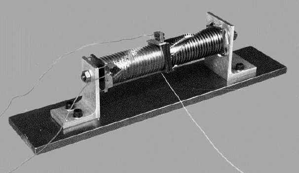
 Design There are 20 steel disks in
each side of this one-way/two-way actuator.
These disks (5 mm thick, outer diameter 46 mm, with a groove of 3 mm deep
and 3.2 mm board) are mounted on SKF deep groove ball bearings. The diameter
of the steel shaft is 10 mm. Eight hard steel balls (diameter is 2 mm)
are used to separate two steel disks. Hard steel balls are held at the
position by a 1.8 mm thickness PTFE ring with eight 2.2 mm diameter punched
holes on it. SKF deep groove ball bearings are separated by 0.1 mm thickness
of steel washers. Therefore each steel disk can rotate freely with very
little friction. Same size of PTFE sleeves used in actuator No. 2 are also
used in this actuator. To avoid the problem of Nitinol wire digging into
gaps between disks, part of the steel disk is cut out. Nitinol wire goes
across disks at this cut-out positions. The geometrical dimension of the
cutting is designed to avoid the Nitinol wire from touching steel disk
as steel disk rotates comparatively by up to 15o. At one side,
the last steel disk next to shoulder is locked with it. On the contrary,
at another side, steel disk can rotate freely in the case of actuation
as a one-way actuator or be locked with the
shoulder after adjustment (by means of some rotation to fit the real length
of Nitinol wire) in the case for two-way actuation.
Design There are 20 steel disks in
each side of this one-way/two-way actuator.
These disks (5 mm thick, outer diameter 46 mm, with a groove of 3 mm deep
and 3.2 mm board) are mounted on SKF deep groove ball bearings. The diameter
of the steel shaft is 10 mm. Eight hard steel balls (diameter is 2 mm)
are used to separate two steel disks. Hard steel balls are held at the
position by a 1.8 mm thickness PTFE ring with eight 2.2 mm diameter punched
holes on it. SKF deep groove ball bearings are separated by 0.1 mm thickness
of steel washers. Therefore each steel disk can rotate freely with very
little friction. Same size of PTFE sleeves used in actuator No. 2 are also
used in this actuator. To avoid the problem of Nitinol wire digging into
gaps between disks, part of the steel disk is cut out. Nitinol wire goes
across disks at this cut-out positions. The geometrical dimension of the
cutting is designed to avoid the Nitinol wire from touching steel disk
as steel disk rotates comparatively by up to 15o. At one side,
the last steel disk next to shoulder is locked with it. On the contrary,
at another side, steel disk can rotate freely in the case of actuation
as a one-way actuator or be locked with the
shoulder after adjustment (by means of some rotation to fit the real length
of Nitinol wire) in the case for two-way actuation.
|
||||
Testing and simulation This
actuator can work both as an one-way actuator
and as a two-way actuator (depend on the set-up).
In the case of one-way actuator, the pre-stretching
of Nitinol wire can be done by simply applying a torque on the middle disk.
On the other hand, in the set-up as a two-way actuator,
pre-stretching one side (at least) of Nitinol wire is still necessary (which
can also be done by simply loading on the middle disk). 0.5 mm diameter
Nitinol wire was used in the actuator instead of 1 mm diameter Nitinol
wire used in the previous two actuators. Working torques used in the test
varied from -0.2 Nm to 0.62 Nm. Over 180o of rotation has been
achieved. This actuator both in one-way and
two-way configurations were simulated by using
phenomenological
constitutive model which including the non-uniform of force in Nitinol
wire.
|
| Design | Testing |
|
|
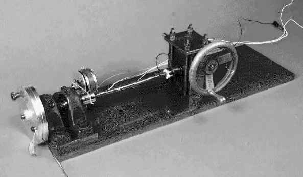
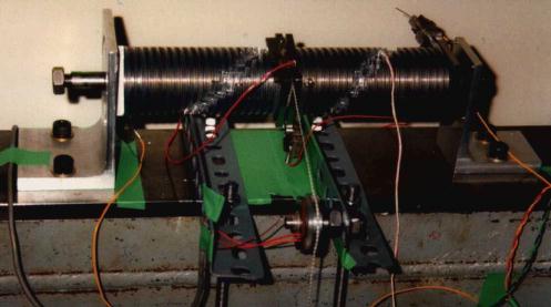
| A constant torque can be applied by means of dead weights
and a pulley, alternatively the pulley can be locked, and a rotation of
one end relative to the other imposed by means of turning wheel of the
worm drive gearbox. The torque is measured by strain gauges on the narrowed
section of the shaft connected directly to the specimen. Rotation of either
end can be measured by a potentiometer, a driven from either of the chucks'
that hold the ends of the Nitinol bar. The active length between two ends
is measured as 130 mm.
Nichrome wire, which is firstly wrapped by polyimide electrical adhesive tape, is used to heat the bar by passing a current through it. Thermocouple is placed on the surface of the centre of the bar. to try and keep the temperature distribution as even as possible the ends of the bars are insulated from the test rig by means of a high temperature, low thermal conductivity epoxy. The Nitinol bar has square mild steel blocks silver soldered onto the ends, these are pinned through as an extra precaution. |
The Nitinol bar used in this actuator is, in fact, with
two-way shape memory, i.e., it can
remember both high temperature shape and low temperature shape.
More interesting thing with this bar is that, very little transformation rotation can be induced by mechanically cycling between 8.1 Nm and -8.0 Nm. However, very huge rotation can be easily achieved in thermal cycling. Some kind of evolution behavior was also found in the actuator to reach a stable performance. Two kinds of experimental results were shown in the above plot.
After several thermal cycling under 2.0 Nm, load was removed for the another four cycles. Approximately 70o of free rotation was obtained finally. They are stable results of thermal cycles under different constant loads. |
Last updated on the 27th of March, 1998
W Huang - mwmhuang@ntu.edu.sg