![]()
![]()
![]()
![]()

Kinematics of Closed-Loop Linkages
Background
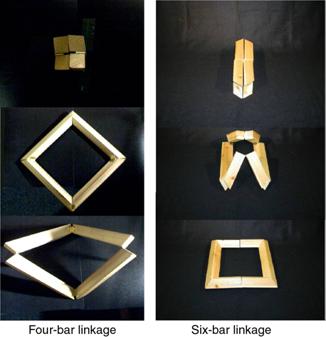
Many deployable structures form single or multiple, often interlaced,
closed loops. Some of these structures form space frames, and have a variety of
applications. Our research is concerned with a kind of deployable structures
that form closed loops that fold into a bundle of bars, using simple hinges.
These structures have potential applications for ultra-lightweight solar
arrays, solar sails, and radar structures. A systematic study of the kinematics
of closed-loop structures is being carried out, including the development of a
scheme for simulating the deployment of both symmetric and non-symmetric
linkages.
Objective
Previous studies on deployable structures use only 2D mechanisms as
basic elements. Very little has been done on 3D mechanisms as geometrically
they are much more difficult to analyse. We aim to develop a scheme that
enables a designer to gain considerable insight into the kinematic
behaviour of 3D closed-loop linkages, from which issues such as structural
sensitivity to imperfections, can be analysed and answered.
![]()
Kinematic Analysis
We define each element of the loop by means of a transformation matrix Ti
and each revolute joint by a transformation matrix Tθi.
The transformation matrix T is a 4 × 4 matrix which can be
expressed as

Here, Ri
is a 3 × 3 rotational sub-matrix which is defined according to the standard
x-convention for Euler angles and vi is the 3 × 1 vector translation. For a closed
loop linkage, we can obtain the following loop-closure condition:
T1 Tθ1
T2 Tθ2 T3 Tθ3 T4 Tθ4
T5 Tθ5 T6 Tθ6 = I
In the equation above,
I is an identity matrix imposing that the loop
should fit together in all configurations, hence (i)
the first and last points are the same, (ii) the axes of rotation of the first
and last revolute joints coincide. This equation can be solved numerically
using a predictor-corrector scheme based on a standard Newton-Raphson iteration. Any solution of
this equation is a possible instantaneous configuration of the structure.
Analytical
Solution and Modelling
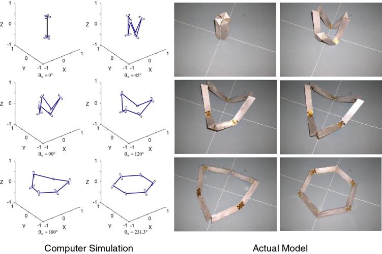
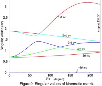
Using the above numerical solution method for the closure equation, we
have analysed the deployment behaviour of a 6-rod linkage first studied by J.M. Hedgepeth, without assuming
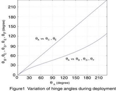
symmetric behaviour. Figure 1 shows the plot of the hinge angles variation
during deployment whilst Figure 2 shows the singular values of the structure kinematic matrix computed during deployment. The behaviour
predicted by the numerical scheme is identical to the actual model as shown
below.
(Movie in AVI format – 6-bar
Linkage 0.65Mb)
![]()
Discussion
The analytical approach provides considerable insight into the kinematic behaviour of closed-loop linkages, from which issues important for design, such as sensitivity to imperfections, can be analysed. It is also become possible to design assemblies with special properties, e.g. frame with some particular dimensions or non-symmetry.
Please follow this link for further details AIAA conference paper.
[ Cambridge University | CUED | Deployable Structures ]
Last updated on
W.W. Gan – wwg20@cam.ac.uk