![]()
Cambridge (UK)
![]()
![]()
Bistable Compliant Actuator
The Cambridge contribution to the SYNCOMECS project is carried out by the Deployable Structures Laboratory (DSL) in the Engineering Department of the University of Cambridge, run by Prof. Sergio Pellegrino.
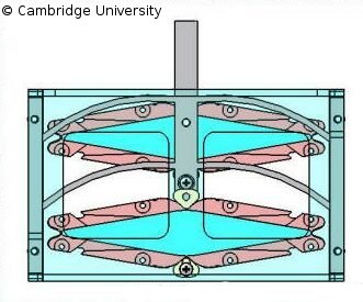
Currently, we are investigating the optimization of a compliant bistable snap-through mechanism which may be used as a benchmark problem, using Samcef Mecano and Boss-Quattro. The original bistable mechanism is illustrated below on the left and is integrated with polymeric actuators developed at MIT to create a digital actuator (shown below on the right).
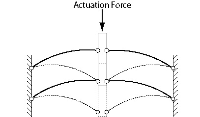
It can be seen that the mechanism consists of four uniformly curved snap-through truss elements connected to a central column and rigid walls by compliant hinges. The curvature (which may be variable) and the cross sectional geometry of each truss element may be altered to tailor the actuation force-displacement profile of the snap-through to match best a given driving actuator profile.
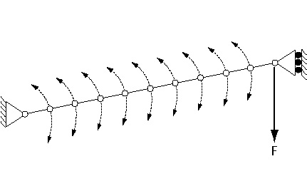
In order to carry out the optimization, we focus on a single snap-through truss element. The geometry of the spline which defines the truss is itself defined by the position of nine internal control points, whose coordinates are parameterised. Further parameters are the thickness of the truss element between consecutive control points. This concept is illustrated below.
For a given actuation force profile Boss-Quattro is able to provide the optimum snap through truss geometry to minimise the error between the actual and desired force-displacement profiles. The desired force-displacement profile (which matches the response of a particular actuator developed at MIT) is shown below.
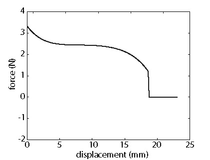
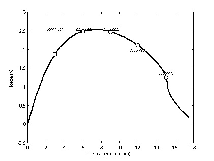
The snap-through truss with uniformly curved members was designed analytically such that the peak resistance force was 2.5 N, which is sufficient to allow actuation by the MIT actuator. This is not a particularly efficient solution, and the optimization is intended to design a truss which matches the MIT actuator profile significantly more closely. The parameterized truss was therefore optimized to have a minimum error at five forces occurring at displacements of 3 mm, 6 mm, 9 mm, 12 mm and 15 mm. The first three were constrained to be less than 2.5 N, and the final force was constrained to be less than 1.3 N. In order to lead the optimization towards the most desirable solution, the fourth force at a displacement of 12 mm was constrained to be greater than 2.0 N.
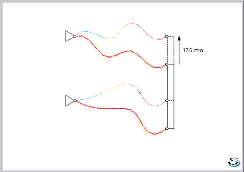
First, a single truss was parameterized as a spline with four internal control points and a single thickness. The final shape of the truss following optimization and the associated force-displacement profile (with the constraints illustrated) are shown below.
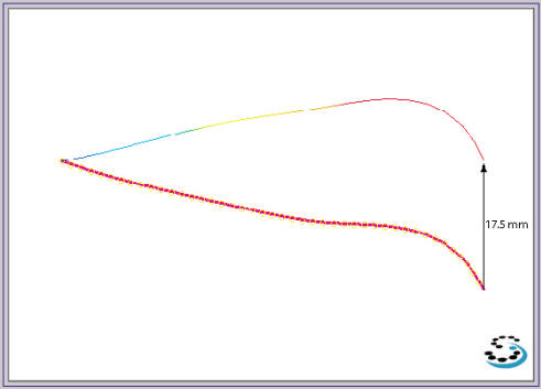
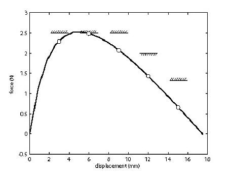
It can be seen that the response of this optimized snap-through truss could be actuated by the MIT actuator, but only four of the five force constraints have been met. The force constraint corresponding to a displacement of 12 mm has been broken. This indicates that it is necessary to refine the parameterization of the truss to allow all the constraints to be observed. The solution obtained by optimizing a strongly parameterized truss element with nine internal spline control points and ten distinct thicknesses is shown below.
In this case, the optimized truss is a shape that is substantially different to that which would have been achieved by conventional analytical techniques. From the response it can be seen that the fourth force constraint has still, in fact, been broken, but by a considerably smaller amount. It can also be seen that the first force constraint is less well observed. The model shown above does not represent a converged optimized solution as in following iterations, the radii of curvature became too small for the solution to converge. It appeared that it was not possible to achieve a better match to the actuator than the two profiles shown above when optimizing a single truss.
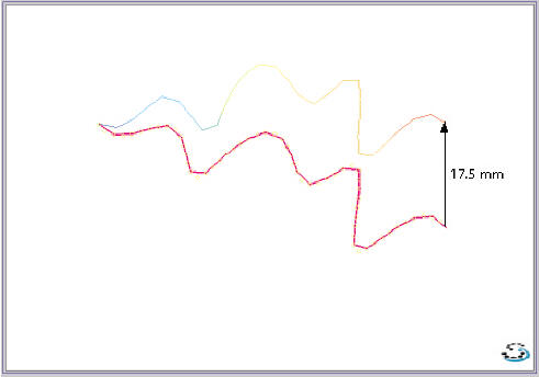
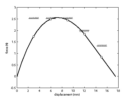
It was therefore decided to optimize one half of the snap-through mechanism (i.e. two truss elements) to see if a better match to the MIT actuator profile could be obtained. This was indeed the case, and the optimized model and associated response are shown below. Each individual truss member was assigned four internal spline control points, and both trusses were assigned the same (constant along the truss) thickness variable.
In this design, all the desired constraints are observed and the truss force-displacement profile is beginning to more closely represent the actuator's profile. This sequence illustrates the substantial design improvements which can be made through optimization.
Website maintained by the University of Cambridge
Last modified, May 2006