To find out more about research and teaching in Civil Engineering please go to our divisional website: https://civileng.eng.cam.ac.uk/
Strategic Aim: To advance the design, construction, and operation of civil and structural engineering systems within the broader context of sustainable and resilient infrastructure and the stewardship of Earth's resources and environment.
Division D is led by Professor Giulia Viggiani and includes the following research groups and centres; the Laing O' Rourke Centre, Geotechnical and Environmental, Use Less, Structures, Sustainable Development, the EPSRC Centre for Doctoral Training in Future Infrastructure and Built Environment (FIBE/CDT), the Centre for Smart Infrastructure and Construction (CSIC), the Computational Statistics and Machine Learning Group and Digital Roads of the Future.
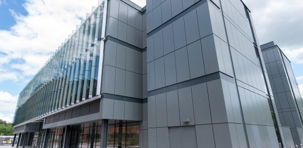
Division D is based across four sites: the Civil Engineering Building (7a JJ Thomson Ave, Cambridge CB3 0FA), the Schofield Centre (High Cross, Madingley Rd, Cambridge CB3 0EF) and the Roger Needham Building (7 J J Thomson Avenue Cambridge CB3 0RB) on the Cambridge West site and the Trumpington Street Site (Trumpington Street, Cambridge CB2 1PZ) in Central Cambridge. Structures, the Laing O'Rourke Centre, the Centre for Smart Infrastructure and Construction part of Geotechnical and Environmental, Digital Roads of the Future, Computational Statistics and Machine Learning Group and the National Research Facilities for Infrastructure Sensing are based in the Civil Engineering Building. The Future Roads Programme, FIBE2 and FIBE3 are based at the Roger Needham Building. Use Less and Sustainable Development are based at the Trumpington Street site. Geotechnical and Environmental are based at the Schofield Centre.