
![[Univ of Cambridge]](http://www.eng.cam.ac.uk/images/house_style/uniban-s.gif)

![[Dept of Engineering]](http://www.eng.cam.ac.uk/images/house_style/engban-s.gif)


The suspension system:

|

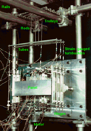
| As the photo of the fully retracted configuration shows, the weight of the array is supported at seven points with one single-point and three double-point suspension elements. The suspension elements consist of steel cables with strain-gauged turnbuckles which are connected to the hinges at one end and to horizontal tubes at the other end. The tubes are linked via rods to trolley pairs which run on horizontal rails. With the turnbuckles the length of the cables can be manually adjusted and with the strain gauges the tension force in the suspension cables is measured. |
Experimental observation:
Experiments have revealed that the variation of the suspension forces in the cables during deployment due to the changing stiffness of the structure and unavoidable imperfections in the experimental set-up is surprisingly high indicating substantial interaction between structure and suspension system.
Computational modelling:
Simulations with computational structural models of the array and the suspension elements have shown that the measured suspension forces differ significantly from the forces predicted for optimal gravity compensation and that the distribution of the weight of the array amongst the suspension points can be optimised by length adjustments at the suspension cables.
Effect of manual length adjustment at the suspension system:
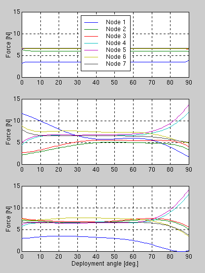
The following graphs show the suspension cable forces at the seven
suspension points (node 1-7) throughout deployment. The
deployment angle is zero and 90 deg. in the fully deployed and
retracted configuration, respectively.

|

| The first graph gives the variation of suspension forces which is required for optimal gravity compensation according to computational results. |

| The second graph shows one out of many other possible suspension force variations which can be measured during deployment depending on the initial length adjustments at the suspension cables. According to the difference between the measured and required suspension forces the necessary changes for the length adjustment at the suspension cables are calculated from the computational models. | |

| The third graph shows the measured suspension forces after the length of the suspension cables has been changed. The corrections have been carried out for the fully deployed configuration (deployment angle equals zero deg.). The improvement of the suspension force distribution for the considered configuration is clearly visible. |
Conclusion:
Since with the present passive suspension system only manual length adjustments are possible, the required corrections can only be carried out for one particular deployment configuration. In order to achieve a suspension force distribution for optimal gravity compensation throughout deployment, it is essential that the length of the suspension cables can be actively controlled during the shape transformation of the solar array structure.
Actively controlled suspension system:
The passive experimental set-up has been converted into an active system equipped with sensors and actuators, see the movies next.
Deployment (click here)
Details (click here)
| Last updated 6th April, 2001 |
![[Back to top]](./backtotop.gif)
|