New Deployable Reflector Concept
This study presents a new deployable structure concept
for a low altitude Synthetic Aperture Radar (SAR) satellite (see Figure
1). The satellite is designed to perform low-cost Earth observation missions
including land hazards, agriculture, forestry, geology, maritime and infrastructure.
The deployable reflector is a functional element of a reflector system which
comprises launch restraint system, supporting structure, and deployable reflector.
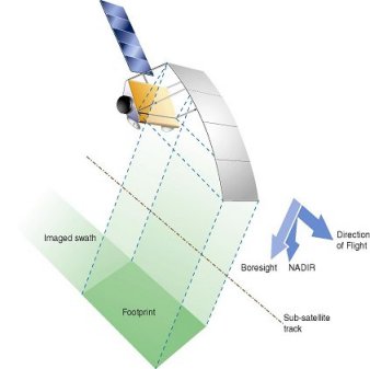

Figure 1: Baseline satellite with classical
hinged panels.
Figure
2 : New concept with curved surfaces
An overall design for a full size reflector is studied, sized for optimal structural performance using the finite element software ABAQUS, and demonstrated by designing, constructing and testing a half-scale high-fidelity demonstrator (see Figure 4).
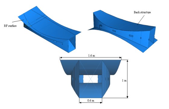
Figure 4: ABAQUS model of half size demonstrator.
The structure is folded by first collapsing it essentially flat and then Z-folding it into a compact package. At full scale the refective surface will be 7.9 m long by 3.2 m wide, and it has been estimated that the whole packaged structure would fit in an envelope of 3.2 m by 1.6 m by 0.3 m. The last dimension depends on the minimum bend radius of CFRP thin sheets, which is estimated theoretically, and also measured experimentally. The performance of the connections between different sheets, made with woven-glass tape, has been determined experimentally. Figure 5 shows packaging process of the demonstrator .
The proposed deployable reflector concept is a "hollow
solid" that comprises curved surfaces formed from carbon-fiber-reinforced-plastic
(CFRP) thin sheets connected by flexible hinges along the edges, and supports
a continuous reflective surface (see Figure 2). The new concept have several
advantages over classical hinged panels in terms of weight savings, high
stiffness, surface accuracy, and potentially very low cost.
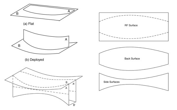
The concept combines the standard cutting pattern technique used, for example, to achieve complex three-dimensional shapes in membrane roof canopies, with the use of thin and yet stiff materials (see Figure 3). The key to forming a cylindrical surface with any required shape is in the cutting/joining profile for the sheets. For a parabolic cylinder, this profile can be found analytically, given the focal length, aperture distance, and offset distance of the reflector. It enables the reflector to have high structural stiffness and stability in deployed configuration (see Figure 4) without having to prestress the structure as required by membranes.
The concept combines the standard cutting pattern technique used, for example, to achieve complex three-dimensional shapes in membrane roof canopies, with the use of thin and yet stiff materials (see Figure 3). The key to forming a cylindrical surface with any required shape is in the cutting/joining profile for the sheets. For a parabolic cylinder, this profile can be found analytically, given the focal length, aperture distance, and offset distance of the reflector. It enables the reflector to have high structural stiffness and stability in deployed configuration (see Figure 4) without having to prestress the structure as required by membranes.
Figure 3: Structural concept on the left and
cutting patterns for CFRP sheets on the right.
An overall design for a full size reflector is studied, sized for optimal structural performance using the finite element software ABAQUS, and demonstrated by designing, constructing and testing a half-scale high-fidelity demonstrator (see Figure 4).
Figure 4: ABAQUS model of half size demonstrator.
The structure is folded by first collapsing it essentially flat and then Z-folding it into a compact package. At full scale the refective surface will be 7.9 m long by 3.2 m wide, and it has been estimated that the whole packaged structure would fit in an envelope of 3.2 m by 1.6 m by 0.3 m. The last dimension depends on the minimum bend radius of CFRP thin sheets, which is estimated theoretically, and also measured experimentally. The performance of the connections between different sheets, made with woven-glass tape, has been determined experimentally. Figure 5 shows packaging process of the demonstrator .
Figure 5: Packaging sequence.
Proposed reflector has a two-stage deployable structure, in which the first stage involves unfolding the sheets from Z-folded configuration whereas the second stage involves the unfolding of flattened reflector to form a hollow solid (see Figures 6). The curvature of the surfaces is determined by the shape of hinge-lines that connects the sheets. Deployment is powered by elastic energy of both the sheets and flexible hinges. High stiffness of the deployed structure comes from thin-walled box type of cross section.
Figure 6: Deployment process.
Immediately after construction of this demonstrator a surface error of 3.8 mm RMS was measured (see Figure 7); this value improved to 3.4 mm by removing the least accurate 25%of the surface area. The surface error increased to 5.1 mm after folding and deployment, but again improved to 3.3 mm by ignoring 25% of the area. The typical mass achievable with this concept is 1.3 kg/m 2 of antenna, which represents a saving of the order of two-and-half times on the previous state of the art. Patent applications on this invention have been filed jointly by EADS Astrium and Cambridge University.
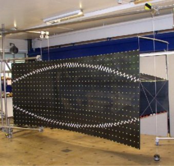
Figure 7: Demonstrator set up for measurement of
surface accuracy.