These web pages describe the design and development of a fully actuated, asymmetrically-bistable, monolithic, energy storing structure (or Jumping Bunny for short). The research was carried out by Matthew Santer and Prof. Sergio Pellegrino of the Deployable Structures Laboratory (DSL) in the Cambridge University Engineering Department (CUED). The research described is a stepping stone towards the development of digital mechatronic intelligent devices, funded by the Cambridge-MIT Institute (CMI).
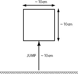
In November 2002, a meeting was held between the DSL and the Field Space and Robotics Laboratory (FSRL) of MIT to discuss advances in the actuation of bistable mechanisms. The motivation for the work described in these pages is the action that arose from this meeting - to design a bistable mechanism that could be made to leap a prescribed distance into the air from a standing start, reset itself, and repeat the process an indefinite number of times. Arbitrary values of 10cm were set for the characteristic length and the jump height of the mechanism.
|
The purpose of making a jumping mechanism is to provide a graphic demonstration that the mechanism is able to do useful work. It is envisaged that the finalised design for the jumping bunny will be used as a structural element in a digital mechatronic system. In this case, the energy release that results in a solitary element jumping could, for example, be used to permit a digital mechatronic system to do work against an external load. Therefore, although steps were taken during the design of the jumping bunny to analyse and maximise the jumping performance (which will be described in the following sections), it must be remembered that this is not the intended final use for the mechanism.
Before introducing the design of the jumping bunny, it is perhaps useful to provide the definition of a digital mechatronic system as recognised by CMI. It is with this definition in mind that the attempts to integrate multiple jumping bunny mechanisms into larger systems, as described below, are put into context.
The mechanical behaviour of a digital mechatronic system is achieved through a larger number of bi-stable configurations, which greatly simplify the system design, control and construction. In the digital mechatronics devices being developed, conventional components such as bearing, gears, motors, etc. would be replaced by monolithic plastic elements driven by polymer actuators. They achieve reliable and precise movements by actuating between discrete stable mechanical configurations using embedded muscle-like bi-stable actuators. Further, because of the large number of binary degrees of freedom, these devices do not require sensors for their control. The formation of digital mechatronics can be seen as the revolution of digital electronics over analogue devices.
The starting point for the design of the jumping bunny mechanism was the collection of bistable mechanisms described by Tyge Schiøler which are based around opposing sets of non-linear tape springs (also known as carpenters' tapes). One of the most promising of these mechanisms is the four-bar four-spring (4B4S) mechanism which is shown below in both of the two stable states.
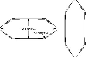 |
This mechanism can be considered to be symmetrically-bistable, by which it is meant that neither one of the stable states is energetically preferential to the other. (This fact may be derived by considering the non-linear behaviour of a tape spring in bending such that the restoring moment of a tape spring bent beyond a critical angle is approximately constant, and recognising that between the stable states, when both pairs of tape springs are in a bent state, all moments effectively cancel each other out.) One of the major effects of symmetric-bistability is that all work done by the mechanism during a transition from one stable state to another must be provided by the actuator that effects the transition.
In order to allow energy to be stored in a bistable structure that can be released as useful work, it is necessary to make one of the stable states energetically preferential to the other. Such a structure can be considered to be asymmetrically bistable, the asymmetry arising from the different amounts of strain energy stored in the different stable states. Any actuator effecting the transition from the less preferential stable state to the more preferential stable state need only move the mechanism out of the first state before the mechanism itself will take over.
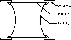
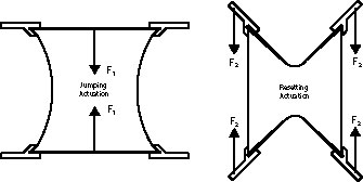
The bistable structure chosen as the basis for the jumping mechanism, primarily due to the absence of sliding parts. Asymmetric-bistability is achieved by replacing one pair of tape springs with regular flat leaf springs having a linear moment-rotation relationship. Two further modifications were made in order to improve the jumping characteristics of the mechanism. (1) The included angle of the corner pieces was changed from obtuse to acute, with the effect that two points instead of one are used to push off from. (2) Cantilevers were added to the corner pieces to amplify the push-off action and to provide an attachment point for the resetting actuators. This new concept is shown below alongside the chosen actuation strategy.
 |
 |
| Concept | Actuation Strategy |
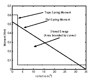
The jumping mechanism was optimised for maximum strain energy storage in the less preferential stable state by the following technique. For a given cross-sectional geometry of tape and flat springs, the moment-rotation characteristics may be idealised as linear (for the flat spring), and constant until a critical rotation and then constant but considerable smaller (for the tape spring). To ensure a lock in the less energetically preferential state, the maximum moment exerted by the flat spring must be exceeded by the snapping moment of the tape spring - a margin of 15% was enforced in the design. For the available tape and flat springs, an fixed corner angle of 55degrees was found to maximise the available jumping energy. A plot of the opposing moments at a single corner is shown below.
 |
Having designed an asymmetrically-bistable structure that has been optimised for jumping, the next stage is to actuate the mechanism such that the transition either way between the stable states may be carried out remotely. This is necessary if the structure is to be used as an element for a digital-mechatronic system. The actuators chosen were shape memory alloy (SMA) springs manufactured by Mondotronics Inc. As previously mentioned, the effect of asymmetric-bistability on the behaviour of the structure is to make one of the bistable states more energetically preferential. Therefore, the transition to this state (the jump stage) is carried out by the mechanism itself. The driving actuator for this stage only has to break the spines of the unbent tape springs.
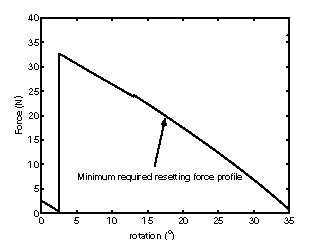
It is possible to generate a force requirement for the resetting actuators (labelled F2 above) by means of a quasi-static virtual work analysis. This states that at any point of the reset cycle, the sum of the work done by any external forces and the work done by any internal forces over an infinitesimal displacement must be zero. One of the major sources of work that must be overcome is the presence of the opposing actuator. This analysis places the force requirement shown below on the resetting actuators (which is shown to be achievable using the SMA springs). 35degrees rotation represents the more stable state, so the graph should be read from right to left.
 |
The analysis of the jump cycle was approached in two different ways. The first (and simpler) of the two was to assume that all of the strain energy stored in the bent flat springs is converted into the potential energy of the final jump height. This is an upper bound prediction - the mechanism clearly cannot jump higher without extra energy input. Clearly there are several potential energy sinks in the system which would result in a reduced jump height, for example: internal kinetic energy that does not contribute to the jump; internal resonances; non-vertical components of motion to name a few. To improve the prediction of the jump height, a full dynamic analysis was carried out based on the idealised model of the jumping bunny (including lumped masses and inertias) shown below.
 |
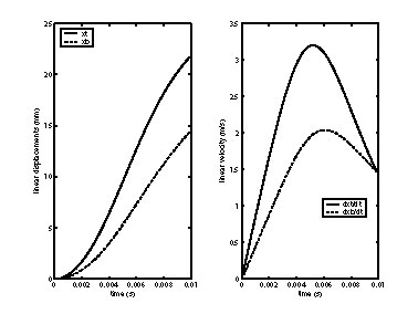
An equation of motion for the mechanism from the point the less stable state was exited to the point of take-off, was derived from a virtual work analysis. This non-linear second-order differential equation was solved using Matlab to obtain the rigid-body velocity of the centre of mass of the mechanism at the point of take-off. The final jump height was then calculated from simple mechanics treating the mechanism as a point mass with known initial velocity under contstant gravitational acceleration. The solution for the linear velocities and displacements of the corners of the mechanism is plotted below. It can be seen that the velocities of the top and bottom corner converge to a single rigid body take-off velocity.
 |
The predicted jump height of 0.111 m achieved by this analysis turns out to be a very good prediction.
A fully actuated model of the jumping 4B4S mechanism was constructed and found to behave according to predictions. Movies of the jump and reset cycles may be seen by clicking on the links below.
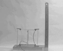 |
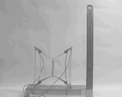 |
| Jump | Reset |
Having created a fully actuated bistable element capable of doing useful work, research is ongoing into the development of digital mechatronic structures based upon this element. The major problem that needs to be overcome is to find a structure based around a quadilateral element (such as the jumping bunny) that is both statically and kinematically determinate. One such potential mechanism is shown below which fulfils all the necessary requirements. Each yellow panel represents a jumping 4B4S element.
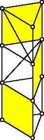 |
Last updated November 2003
M.J. Santer - mjs204@eng.cam.ac.uk